Introduction
Operational Amplifiers (op-amps) are foundational components in analog electronics, and the inverting amplifier is one of their most iconic configurations. Through simulation platforms like NL5, learning and verifying these circuits becomes intuitive and visual. In this video walkthrough, the inverting amplifier is modelled, simulated, and validated using NL5 providing both theoretical insight and practical application.
Understanding the Inverting Amplifier
The inverting amplifier configuration uses an op-amp with a feedback resistor (Rf) and an input resistor (Rin) connected to the inverting terminal. The non-inverting input is grounded. The voltage gain of the amplifier is:
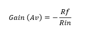
This negative sign indicates a 180-degree phase shift – i.e., the output is inverted with respect to the input.
Simulation Setup in NL5
NL5 is a circuit simulator ideal for visualization of circuit behaviour. The simulation shown in the companion video demonstrates:
Component Placement: Op-amp block, resistors (Rf and Rin), DC power supply, AC voltage source.
Connections: Rin connects the input signal to the inverting input, while Rf connects the output back to the inverting input (feedback path). Non-inverting input is grounded.
Voltage Source Input: A sine wave voltage source (vin) provides a 1V peak input signal for amplification.
Virtual Ground Principle: Highlighted through the behavior of the inverting terminal in simulation.

Simulation Results and Observations
1. The simulation illustrates:
2. Input voltage of +1V results in –3V output, demonstrating the expected gain.
3. Changing resistor values dynamically reflects in the output, reinforcing the proportional gain formula.

Practical Use Cases of Inverting Amplifiers
| Application | Description (with brief explanation) | Examples (aligned one-to-one) |
| Audio Systems | • Adjusts signal gain for volume control • Shapes frequency response (bass/treble) • Inverts phase if needed | • Audio mixers (combine signals) • Equalizers (tone control) • Headphone amps (boost output) |
| Sensor Signal Reading | • Boosts tiny voltages from sensors • Inverts polarity if required by system • Conditions signals for ADC | • Thermocouple amplifiers (temperature) • Photodiode circuits (light detection) • Strain gauge (pressure sensors) |
| Active Filters | • Builds filters for specific frequency ranges • Controls which frequencies are to be passed or blocked • Improves signal clarity | • Crossover filters (split audio bands) • ECG/EEG filters (remove noise) • Anti-aliasing filters (before ADCs) |
| Mathematical Operations | • Integrates signal (accumulates input over time) • Differentiates (detects rapid changes) • Adds/subtracts voltages | • Triangle wave generator (integrator) • Edge detection (differentiator) • Summing amp (audio mixing) • ECG subtractor (noise rejection) |
Why Simulate with NL5?
| Benefit | NL5 Feature |
| Real-Time Feedback | Observe changes in voltages instantly. |
| Ideal & Practical Models | Use ideal op-amps or include non-ideal effects. |
| Interactive Learning | Strengthens component knowledge (e.g., resistors, op-amps, capacitors). |
Key Takeaways from the Video
1. Inverting amplifier gain = -Rf/Rin
2. Simulation confirms theory and highlights practical design.
3. Helps in debugging, understanding transient response, and preparing for hardware implementation.
Conclusion
The NL5 simulation of an inverting amplifier showcases not just the power of analog circuit simulation but also reinforces the fundamentals of op-amp behaviour. This approach is invaluable for students, hobbyists, and engineers aiming to solidify their grasp of analog electronics. The video makes it clear: hands-on simulation leads to deeper conceptual mastery.