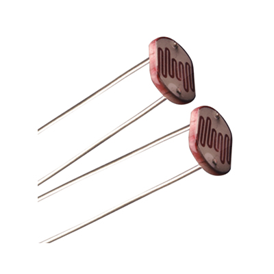
A passive component, also known as photoresistor, semiconductor photoresistor, photoconductor, or photocell, does not require any external voltage supply for it to work.
Used to detect light levels, for example, in automatic street lights, automatic security lights, fire or smoke alarms, burglar alarms, toys, cameras, Automatic Head Light Dimmer, Automatic Bedroom Lights, Automatic Rearview Mirror, etc.
Their resistance decreases, from several thousand Ohms in the dark to only a few hundred Ohms, as the light intensity increases.
In the dark and at low light levels, the resistance of an LDR is high and little current can flow through it.
Types of LDRs:
1. Intrinsic LDRs
2. Extrinsic LDRs.
Extrinsic LDRs are widely used because the variation in the resistance for the variation of light is high and so accurate.
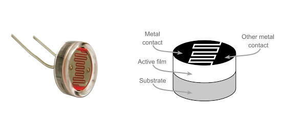
It is made from a piece of an exposed semiconductor material such as Cadmium Sulphide(CdS).
Cadmium sulphide is used because its spectral response closely matches the human eye and can be controlled using a simple torchlight.
Its electrical resistance changes by creating hole-electron pairs, when light falls upon.
LDR CONSTRUCTION

LDR SYMBOL:

LDR Characteristics:

How to Use An LDR in an Application:
In any application, an LDR is used in series with a resistor, as a voltage divider circuit. A fixed voltage is applied to the voltage divider circuit.
Application Circuit Diagram:

When the light falls on the LDR resistor, its resistance decreases and the current through the series circuit increases and so the drop across the resistor R2 , ie, Vout also increases.
This output may be given to a microcontroller to measure the light intensity or to control the necessary device.
Or in simple it may be given to the base of a transistor. This transistor will be turned on and so the LED glows, the moment it crosses the threshold level. It may be used to drive a relay. Using a potentiometer instead of R2 and by adjusting it the threshold level can also be varied as shown below. Transistor BC547 can be used instead of BC557
An LDR Circuit to turn ON an LED:

LDR Specifications
Several important specifications to be considered when designing LDR based electronic circuit design. They are,
Max Power Dissipation :
The max. power it can dissipate within a given temperature range.
Derating may also be applicable above a certain temperature.
Maximum Operating Voltage :
The max. operating voltage that can appear across it.
This is typically specified at 0 lux, i.e. darkness
Peak Wavelength :
The wavelength of maximum sensitivity, specified in nm
Curves may be provided for the overall response.
Resistances When Illuminated :
The min. & max. resistances under certain light conditions, often 10 lux. &
a typical likely to be encountered condition, e.g. 100lux. are given.
Dark Resistance
It is specified at no illumination, after a given response time.
Because it takes a while for the resistance to fall as the charge carrier recombine
Photoresistors are noted for their slow times.
EXAMPLE SPECIFICATIONS F AN LDR
Max power dissipation : 200mW
Max voltage @ 0 lux : 200V
Peak wavelength : 600nm
Min. resistance @ 10lux : 1.8kΩ
Max. resistance @ 10lux : 4.5kΩ
Typ. resistance @ 100lux : 0.7kΩ
Dark resistance
after 1 sec : 30KΩ
after 5 sec : 250KΩ
If you need further help and support to select one of these feel free to always reach us out through our webstore and as always we would be happy to support !


