INTRODUCTION
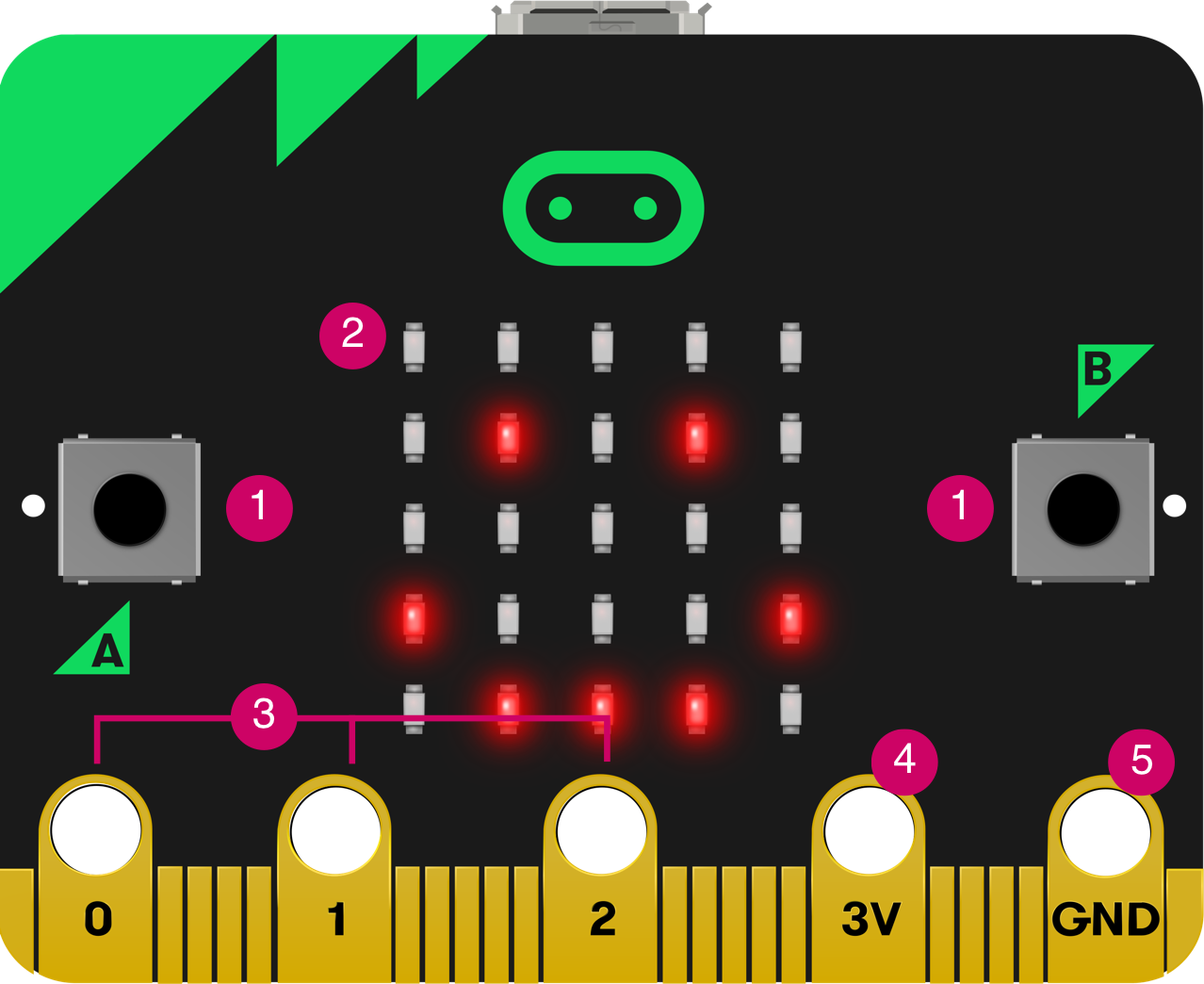
The micro:bit hardware is based on the Arm-Mbed platform. It has an application processor with lots of on-chip peripherals. Some off-chip peripherals are also connected to this chip. There is an interface processor connected to the application processor, and it is the interface processors’ job to manage communications over the USB and to support the drag-and-drop code-flashing process. The interface processor does not connect or communicate to any of the micro:bit peripherals.
SPECIFICATION
- nRF51822 – Application Processor
- NXP KL26Z – Interface Processor
- ST LSM303AGR – Motion Sensor
- 2.4GHz antenna(Bluetooth, radio)
- Edge connectors(5pins)
- 5 X 5 LED Matrix
- Micro USB
- Reset button
- Two user buttons
Component List.
| Microbit | Click Here |
| L293D | Click Here |
| Motor | Click Here |
| Jumper Wire | Click Here |
L293D MOTOR DRIVER
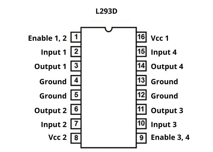
The L293D is a two-channel (DC or Stepper)motor driver IC that can be used to control the direction of motors connected to it by changing the polarity of the inputs given to it.
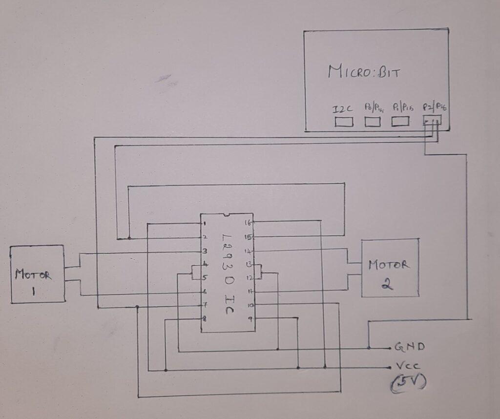
Pin1 is the enable pin, to activate the input1 and input2. And pins 2 and 7 are the input terminals to the motor in channel1. The output is taken through pins 3 and 6. Pin8 is the supply voltage terminal and has two ground pins 4 and 5. Pin9 is the enable pin used to activate the pins 10 to 16 for the channel2 motor.
The diodes are connected in H-bridge format so that no reverse current flows through the circuit due to the rotation of the motors.
CONTROLLING TWO DC MOTORS USING L293D AND MICROBIT
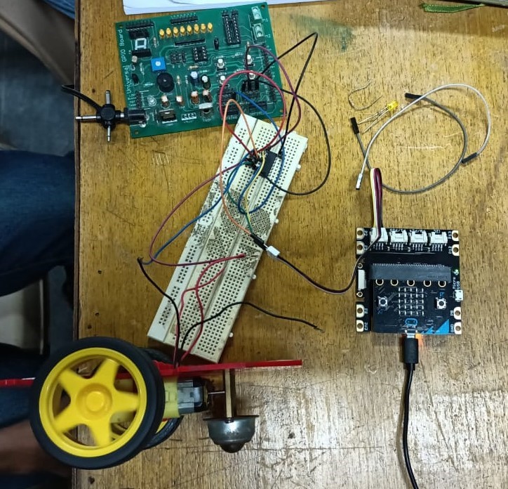
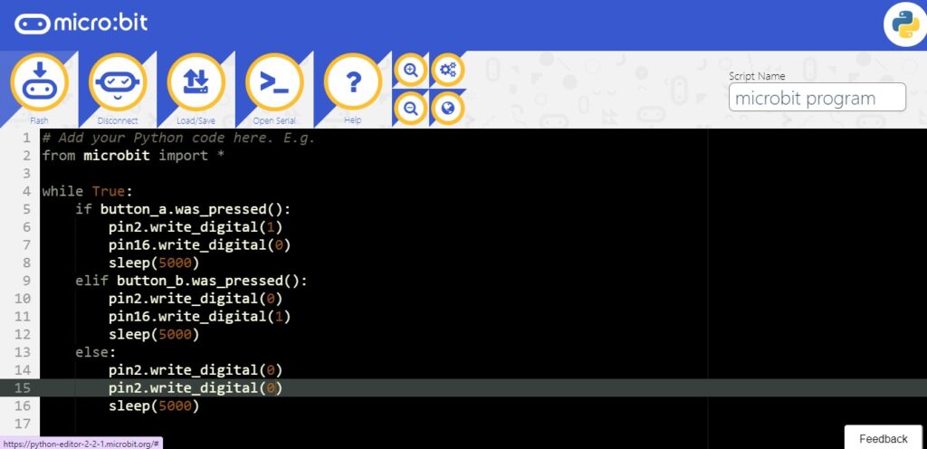
In the above picture, two DC motors are controlled using an L293D motor driver, the microcontroller used to control the circuit is micro:bit and the voltage is regulated to the circuit using the power supply breakout. The micro:bit is programmed using the micro python code to control the direction of the two motors. A grooved shield is used to connect the micro:bit to the circuit.
CODE
CIRCUIT DIAGRAM
More information please do mail us @ info@tenettech.com


