Frequency Modulation is a type of Angle Modulation in which the frequency of the carrier wave is varied in accordance with the instantaneous value of the message signal while keeping the amplitude and phase as constant.

Implementing Wide Band Frequency Modulation (WBFM) Transceiver
The WBFM Transceiver is implemented using the GNU Radio’s “WBFM Transmit” and “WBFM Receive” blocks, the flowgraph of WBFM transceiver consists of a Wide Band FM Transmitter section and Wide Band FM Receiver section in a loop-back System.
Here, the WBFM Receiver section also exploits the capabilities of the GRC filter blocks in reducing the noise from the received signal and is equipped with a selector block to establish a comparison between the filters.

Block Parameters:
Audio Rate: This is the sample rate of the input audio stream.
Quadrature Rate: This is the sample rate of the output audio stream in WBFM Transmit block whereas in WBFM Receive block this is the sample rate of the input complex baseband signal.
Tau: The Pre-emphasis time constant and the default value is 75e-5 (float).
Max Deviation: The maximum frequency deviation in Hertz and the default value is 75e-3 (float).
Preemphasis High Corner Freq: This is the high frequency at which to flatten Preemphasis, here the value less than zero i.e., (<0) implicates the default value of 0.952*quad_rate/2.0 (float).
Audio Decimation: This is the decimation factor for down sampling the complex baseband signal in order to meet the desired sample rates of the audio.
Steps Employed in WBFM Transceiver Implementation
Step 1: Estimating the Frequency Components of the Audio Being Transmitted
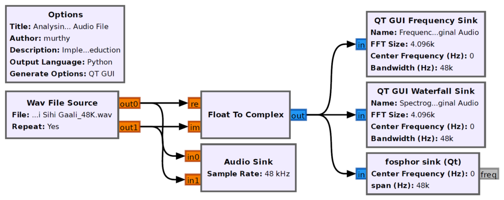
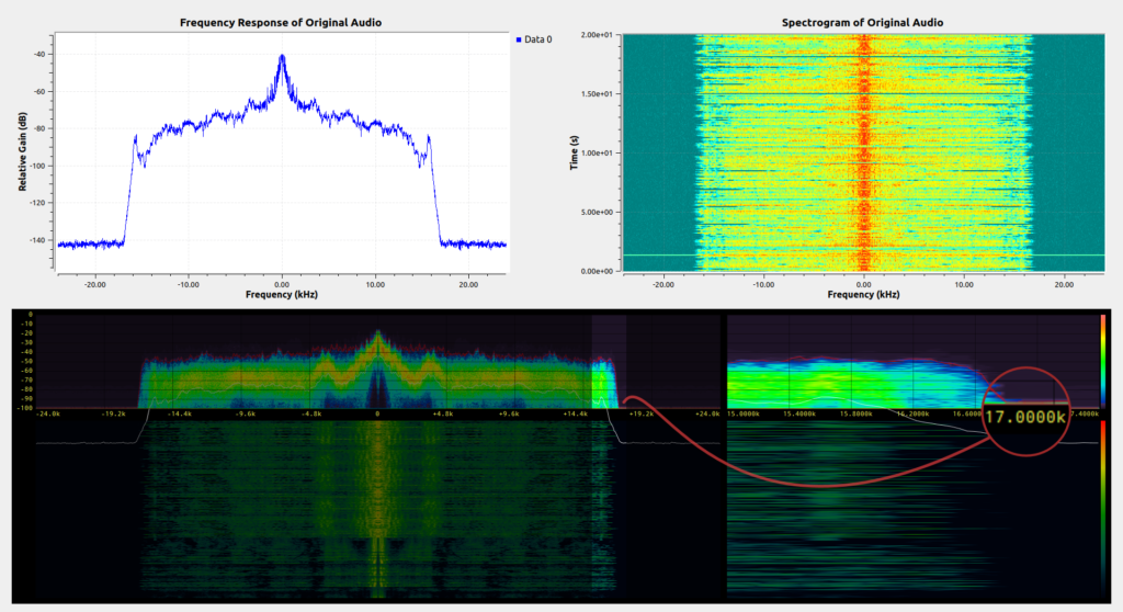
Here, the frequency components of the audio being transmitted have been analysed in order to have an estimate for employing the filters at the receiver end.
Flow Graph for Determining the Frequency Components of the Audio
Step 2: Determining the Unwanted Frequency Components in the Audio Being Transmitted
The spectrogram of the audio shows the frequency extending up to 17 KHz. So, to further estimate the frequency contents of the audio being transmitted, the audio components are further divided into smaller chunks as shown below in order to eliminate unwanted frequency elements.
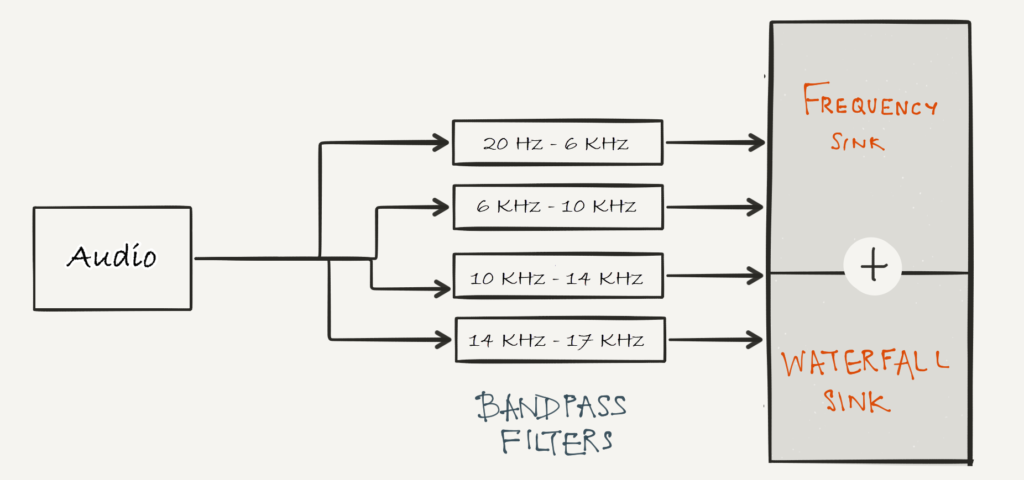
In the figure, it can be observed that the audio is divided into four chunks for better estimation of the unwanted frequency components. Here, 20 Hz is the minimum frequency component which human can hear and 17 KHz is the maximum frequency of the transmitted audio (in this case).
Flow Graph for Determining the Unwanted Frequency Components of the Audio
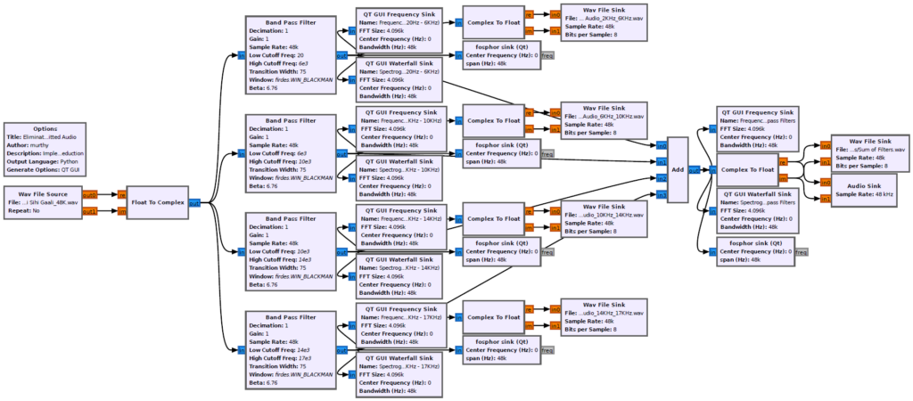
The response of the Band Pass Filter allowing the frequency components between 20 Hz and 6 KHz is as shown below,

The response of the Band Pass Filter allowing the frequency components between 6 KHz and 10 KHz is as shown below,

The response of the Band Pass Filter allowing the frequency components between 10 KHz and 14 KHz is as shown below,

The response of the Band Pass Filter allowing the frequency components between 14 KHz and 17 KHz is as shown below,

Flow Graph for Determining the Unwanted Frequency Components of the Audio by Designing an FIR Filter
GNU Radio also comes equipped with a graphical “Filter Design Tool” which can be found at “Tools 
An FIR Filter is a filter whose impulse response is of finite duration as these filters settles down to zero in finite time. The FIR filters are fast and easier to design & implement on a digital hardware.

Designing the FIR Filters


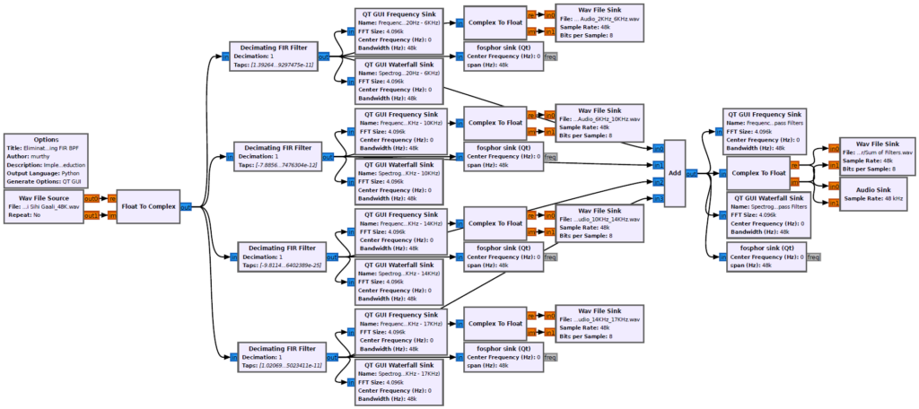
The response of the FIR Band Pass Filter allowing the frequency components between 20 Hz and 6 KHz is as shown below,

The response of the FIR Band Pass Filter allowing the frequency components between 6 KHz and 10 KHz is as shown below,

The response of the FIR Band Pass Filter allowing the frequency components between 10 KHz and 14 KHz is as shown below,

The response of the FIR Band Pass Filter allowing the frequency components between 14 KHz and 17 KHz is as shown below,

Step 3: Implementing WBFM Transceiver
Here, a Wide Band FM Transceiver is implemented which transmits an Audio using the GNU Radio’s “WBFM Transmit” block and the transmitted signal is captured and received using the GNU Radio’s “WBFM Receive” block.
The transmitted Audio file contains the frequency components extending up to 17 KHz, after dividing the audio components into four parts such as
- Low Frequency Component (20 Hz – 6 KHz)
- Mid Frequency Component (6 KHz – 10 KHz)
- High Frequency Component (10 KHz – 14 KHz)
- Very High Frequency Component (14 KHz – 17 KHz)
It is observed that the most of the important frequency elements are present inside the Low Frequency Component (20 Hz – 6 KHz) Range.
Since, most of the useful frequency elements are present inside the “Low Frequency Component (20 Hz – 6 KHz)” range, the filters at the receivers end is made to receive only the frequencies from 20 Hz – 6 KHz range.
Flow Graph for WBFM Transceiver
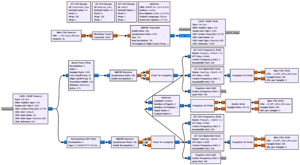
Description of the Flow Graph:
- An Audio file having a sample rate of 48 KHz, is fed to a “WBFM Transmitter” block which is having a quadrature rate of “48 KHz * 4 = 192 KHz” Samples per second.
- The 192 KHz up-converted samples are then transmitted by an USRP using the “UHD: USRP Sink”. The transmitted Audio signal is received by the same USRP hardware using the “UHD: USRP Source” in a loop-back system with a center frequency of 87.5 Mhz.
- The received 192 KHz samples are then passed to a “Decimating Band Pass Filter” and to a “Decimating FIR Filter”, which allows only the frequencies from 20 Hz – 6 KHz range. Here, the decimation factor is set to 4, in order to down convert the 192 KHz samples to 48 KHz samples.
- The output of the filters are fed to the “WBFM Receiver” block, and the samples coming out of the receiver is passed to a “Selector” block in order to have the comparison of the response of the Band Pass Filter and FIR Filter.
- A variable named “Switch” is used for the selector block. So, When “Switch = 0“, the response of the Band pass filter is received, and when “Switch = 1“, the response of the FIR Filter is received.
The response of the WBFM Receiver having a Band Pass Filter with passband between 20 Hz and 6 KHz in the receiver section is as shown below,

The response of the WBFM Receiver having an FIR Band Pass Filter with passband between 20 Hz and 6 KHz in the receiver section is as shown below,

Conclusion
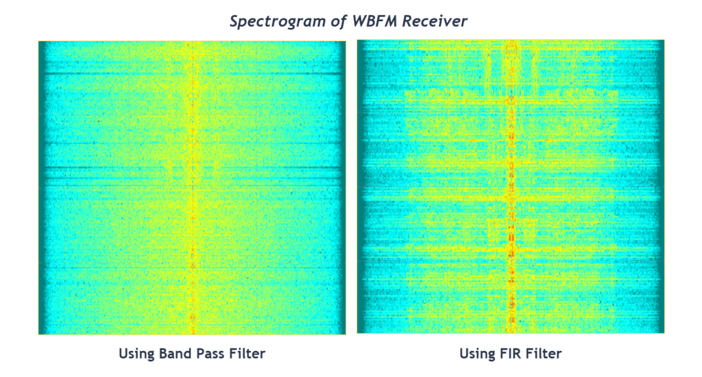
By visually comparing the spectrum of the band pass filter, it is observed that the response of the FIR Filter contains more significant frequency elements when compared to the Band Pass Filter and also by listening to the received audio files, the audio received from the FIR Filter is much clear when compared to the audio from the Band Pass Filter.
For details, contact: info@tenettech.com


