In the previous blog [1], we have covered the installation of physical protocol stack namely eNodeB and UE using SRS (Software Radio System) and further tried to generate the virtual LTE network . This blog is basically a continuation to the previous blog. So if you have not installed the stack, Please refer the previous blog first [1].
In this blog we shall look into following parameters:
- Understanding the importance of ARFCN and its calculation for Uplink and Downlink frequency
- Modification of ARFCN for interfacing the User Interface (UE) with the eNodeB
- Analysis of the Physical parameters between the UE & eNodeB
What is ARFCN?
The ARFCN abbreviated as Absolute Radio Frequency Channel Number (ARFCN) is defined as a unique number given to each radio channel in a mobile network. The ARFCN can be used to calculate the exact frequency of the radio channel probably the uplink and the downlink frequency where uplink frequency is the frequency from mobile device to the Base station and downlink frequency is the frequency from the base station to the mobile system.
ARFCN mainly identifies two separate radio carriers, I.e. uplink and downlink in GSM frequencies.
UARFCN: It is abbreviated as UTRA Absolute Radio Frequency Channel Number identifying the two separate radio carriers in UMTS frequencies.
EARFCN: It is abbreviated as EUTRA Absolute Radio Frequency Channel Number identifying the two separate radio carriers in LTE frequencies.
For Apple users, you can call on the number *3001#12345#* and you will get the image indicating the field test of your mobile device.
Follow the step shown in an image for identifying your mobile ARFCN.
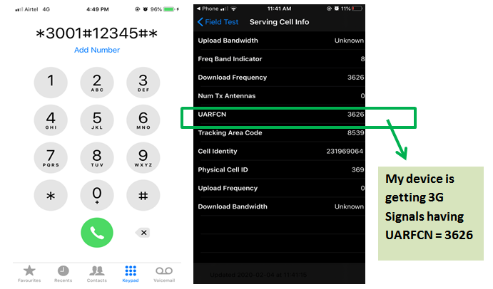
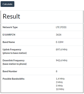
Further there are many online ARFCN calculators, which will help you in calculating the Uplink and Downlink Frequency. For trial, refer the link mention below:
https://www.cellmapper.net/arfcn
Hence my device is having the following Uplink and downlink frequency as mentioned below. From the image mentioned below ,we can observe that in the mobile communication , Downlink frequency is greater than the uplink frequency which is totally opposite to the satellite communication system .As mobile device cannot consume more power because it may lead to over heating of a device further ending up to damage of your mobile devices but eNodeB on vice versa can have more power .
Modification of ARFCN for interfacing the User Interface (UE) with the eNodeB
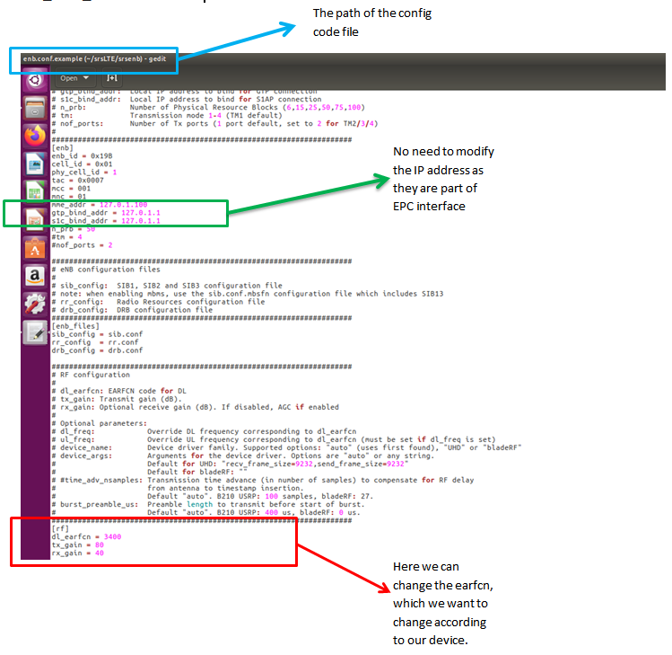
While running the srsenb, the network will by default try to search user interface supporting the uplink frequency = 2560 MHz and downlink frequency = 2685 MHz with ARFCN = 3400 .But In order to interface the mobile device in India, we need to change the ARFCN from the code.
Follow the steps below to modify the ARFCN from the code:
Step 1:
In the srsLTE directory, click on the srsenb

Step 2 :
In srsenb, there is enb.conf.example code file which need to be modified for changing the parameters.

There are two important sections which are modified namely the [eNB] and [RF] sections in the config file for interfacing the UE with the eNodeB. In the eNodeB we can modify the following settings for the Cell ID, TAC, Physical Cell ID, MCC, MNC, ARFCN and all that other good identifying stuff. There is an IP addresses mentioned which need not to be changed as these are the part of the EPC interface.
Following up the:
mme_addr = 127.0.1.100
gtp_bind_addr = 127.0.1.1
s1c_bind_addr = 127.0.1.1
Step 3 :
Once the necessary changes are made, you can interface the SDR with the Host system and run the command sudo srsEPC and srsenb in different terminal in one host system and srsue in the other host system. We get the result as discussed in the next section.
Analysis of Results obtained:
We will get the eNodeB results as mentioned below, once the device is interfaced with the eNodeB.
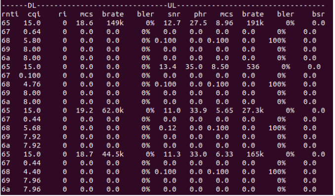
It describes both the downlink and uplink physical parameters between the eNodeB and UE (In my case UE is the other host system).
Let’s now discuss on the following parameters:
- RNTI: RNTI stands for Radio Network Temporary Identifier. As the name implies, it is a kind of Identification number which differentiate one specific radio channel from other radio channel and one user from another user. It will be always unique.
- CQI: CQI stands for the Channel Quality Indicator. It is used by the mobile to indicate the channel quality to the eNB. CQI number will be always between 0 to 15 with 0 & 1 indicating the poorest channel quality and 15 indicating best channel qualities.
- RI: RI stands for rank indication which is one of the control information that a UE will report to eNodeB on either PUCCH or PUSCH based on uplink scheduling.
- MCS: MCS stands for modulation and coding schemes. It defines two important aspects namely: 1. Code rate, 2. Modulation.
- BLER: Block error rate ratio of the number of erroneous blocks to the total number of blocks transmitted on a digital circuit.
- PHR: PHR is a MAC control element that the UE uses to tell the eNB, how much power it has been left with currently.
- BSR: Buffer status reporting indicating how much data are buffered in the UE’s memory. For uplink radio resource allocation, a UE needs to send the BSR to the eNB to indicate the amount of data in the UE that need to be transmitted.
- BRATE: It stands for the Bit rate indicating number of bits transmitted per second.
For detail regarding the product, refer: info@tenettech.com

