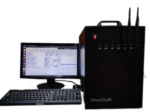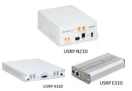
This Application Note will demonstrate the interfacing steps needed for configuring the USRP series with the host system via Ethernet.
Probably this Note focuses on the USRP N, USRP X, USRP E series which are interfaced with the host system using Ethernet.
Follow the step mention below :
Step 1:
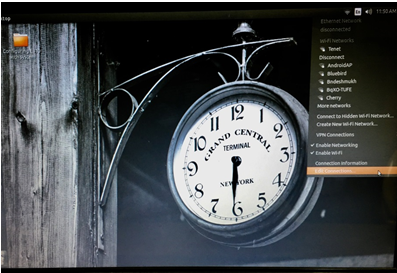
First step is to create an Ethernet network . On the right hand corner in Ubuntu operating system, click on the Wi-Fi internet symbol. In the given terminal , double click on the edit connection to open the Network connection page as shown below:
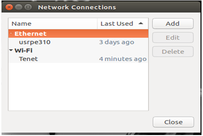
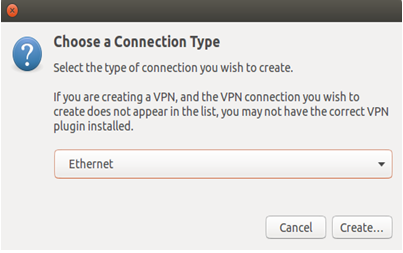
Click on the ADD button from the Network connection page and select the type of internet connection.
Step 2:
This article mainly focuses on the Ethernet based internet services, thus selecting the network to Ethernet and click on create in order to initialize the network.
Step 3:
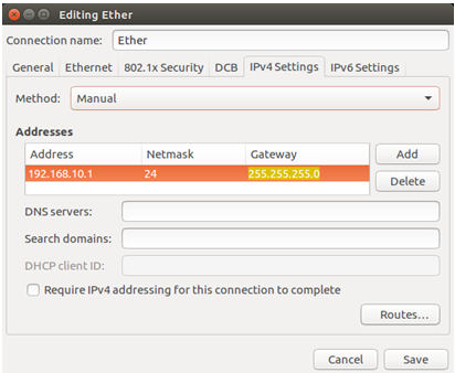
This step defines the IP address needed for the Ethernet based internet services. The network generated is renamed to Ether (It can renamed anything as per your requirement).
The default IP address of the USRP N and USRP X is 192.168.10.2. The default IP address of USRP E series is 192.168.10.42.
You will need to configure the host’s Ethernet interface with a static IP address to enable communication. For maximum throughput, only one Ethernet interface is recommended per USRP devices. The multiple USRP devices can be connected to single host system via a Gigabit Ethernet switch. In any case, each Ethernet interface should have its own subnet, and the corresponding USRP device should be assigned with a unique IP address in that subnet. For another USRP device, the IP Address till 192.168.10 will remain same, thus modifying only the last sub section of the IP address. Hence connecting all the devices within the same network. Now communication is possible with all the USRP devices within a same network.
While converting the subnet masking (255.255.255.0) to binary format, we get 11111111.11111111.11111111.00000000. , I.e. we get 24 one’s. Hence Net masking represents the bit length of subnet mask. Therefore it is also indicated as 24. It is a 32 bit number which masks an IP address and divide it with the network address and the host address. Hence in IPv4 version we can also indicate the IP address as 192.168.10.1/24 which indicates that the device is having an IP address 192.168.10.2 with subnet mask as 255.255.255.0. The IP address starting with 10, 172, 192 are private IP address which are used in local Networks.
For Example:
USRP 1: 1) IP Address –> 192.168.10.1 with subnet mask 255.255.255.0
USRP 2: 1) IP Address –>192.168.10.2 with subnet mask 255.255.255.0
Example
Consider an Example of Implementation of QPSK in Gnu radio and finally validating using USRP X310.
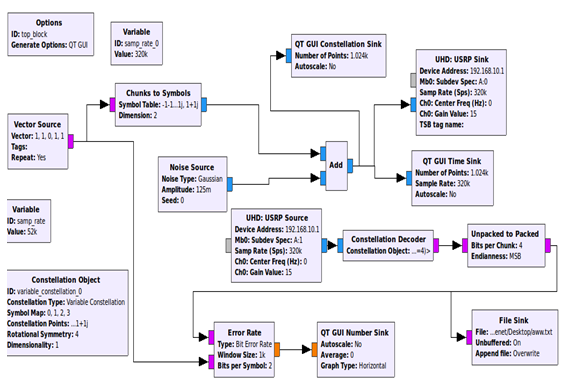
The figure above indicates the Gnu radio Flow graph for the implementation of QPSK using USRP X310. The interfacing of USRP device with the host system and Gnu radio is done using Ethernet. The IP configuration for USRP X310 devices is set to 192.168.10.1 with the subnet masking as 255.255.255.0. This experiment is implemented with a loop-back condition i.e. same USRP X310 devices is used for the transmission and reception of signals. Hence the UHD: USRP Sink and UHD: USRP Source is connected with the same IP address. USRP X310 has two distinct channels namely channel A and B, therefore in this experiment, we are operating the transmission and reception of signals with first channel where A: 1 indicate the transmission and reception of signals through the channel A. This Post focuses only on the Interfacing of USRP series with the Gnu radio and the host system, Hence results can be further implemented once device is properly interfaced.
One can verify whether the device is interfaced, by following the simple commands in the terminal as shown below:
uhd_find_devices
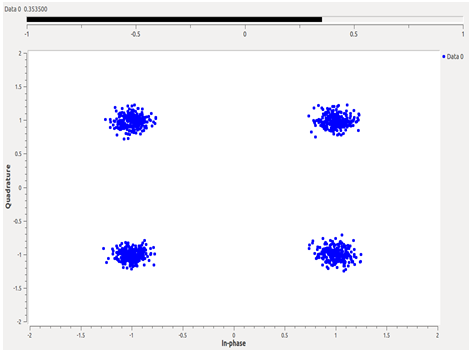
The figure above indicates the constellation point representation of QPSK modulation techniques. The constellation point defines the number of bits transmitted per messages. The above result is evaluated with the real time channel environment having signal to noise ratio SNR as 15 db. The figure below indicates the time domain representation of random signals with red color indicating the Gaussian Noise with 0db. With the increase in SNR, the effect of Gaussian noise on the signals will reduce.
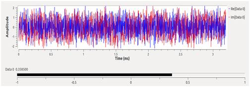
The bit error rate is noted as 0.358, which can be further reduced by having proper channel estimating equalizer. Hence this application post successfully aims in providing complete information about how to configure the USRP series with the host system via Ethernet.
Enjoy Implementing !


