ARM UNIVERSITY KIT
Today let us talk about most awaiting topic called “ARM University kit“. Since it is a huge topic to discuss, let us take it episode by episode. In this blog let me try to introduce you to our parabola of University kit specially designed by Tenet Technetronics. This kit has multiple features, and works for many number of programs.
We all know that Millions of electronic gadgets around the world invade in and out of our daily life and we have become completely dependent on them for performing most of the work. The arm processor cores used in most of these devices follows arm architecture. There are several embedded architecture in use such as Arm arch by Arm ltd, Atmel’s AVR architecture and many more.
ARM is nothing but Advanced RISC Machine Arm holding develops the instruction set and architecture for arm based products but Arm do not manufactures IC’s.
Do you Know what makes Arm so popular??
- Smallest CPU die size
- Low cost
- Low power consumption
- High performance
Let me brief about Arm family before entering to the main core of the university kit, In that different ARM Core’s are as shown below
By considering the Arm Cortex Processor family, different types of cortex are
Again in Cortex M family we are Cortex M3 as an MCU for the Arm University kit

The Micro controller unit is STM32 Nucleo, board provides an affordable and flexible way for users to try out new concepts and build prototypes with the STM32 microcontroller, choosing from the various combinations of performance, power consumption and features. For the compatible boards, the SMPS significantly reduces power consumption in Run mode.
ARM Cortex-M3 72 MHz, 128-KB Flash, 20-KB SRAM. STM32 Nucleo-64 development board with STM32F103RB MCU, supports Arduino and ST morpho connectivity.


Nucleo STM32-F103RB
The arm university kit designed by the Tenettech is shown below:

This kit is complete package to cover all the experiments prescribed by the VTU and other university syllabus.
All the components are internally connected, just an plug and play option makes the student most comfortable to conduct the experiments.
The base board consists of
- Digital sensors
- 4 LEDs
- Buzzer
- 4 Pushbuttons
- DC Motor with Driver
- Stepper Motor with Driver
- 7-segment Display
- Analog sensors
- LM35
- Potentiometer
- Communication
-
- Serial communication (UART)
- SPI
- I2C
- Wi-Fi ESP8266 (Optional)
- Additional interfaces
-
- Keypad
- LCD 16×2
Procedure to start a new Project:
Step 1: Double click on Kiel-Mvision desktop icon, GotoàProject, Selectà New Mvision project.

Step 2: Enter the File name, create the project file.

Step 3: Select the device for the target, ARMà STMicroelectronicsà STM32F1seriesà STM32F103à STM32F103RB
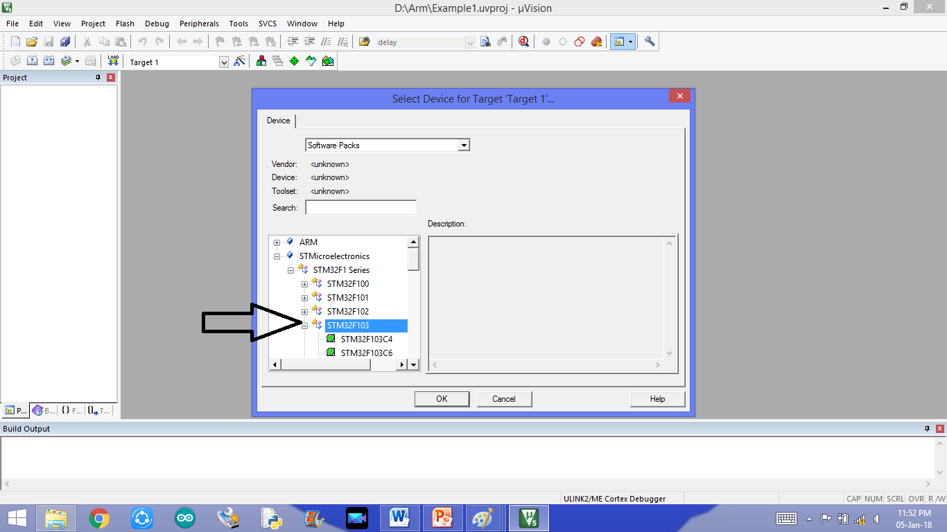
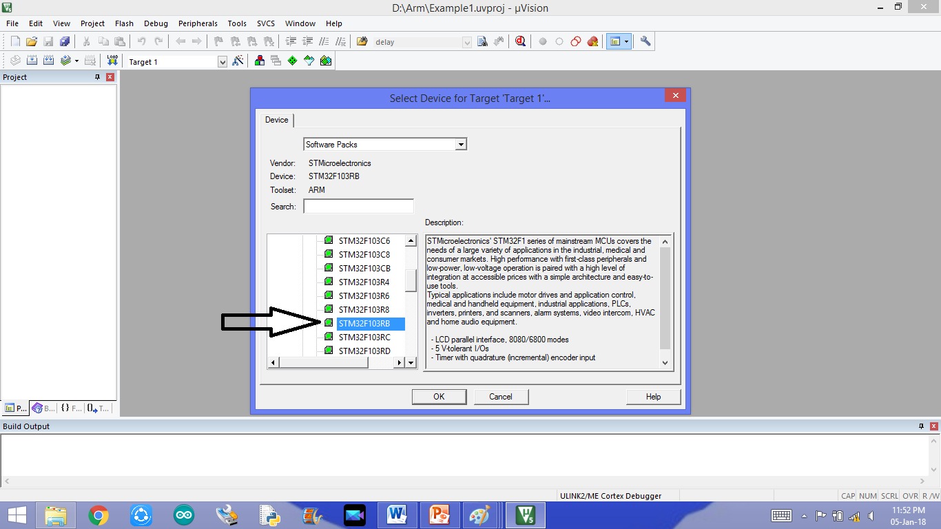
Step 4: Go-to à CMSIS, select à Core, Go-to Deviceà Select startup, press ok.

Step5: Target is created

Step 6: Add file to the source group by right click on Source Group

Step 7: Select the file type i.e C file, enter the program file name i.eBlinkled. Then ADD the file and close it
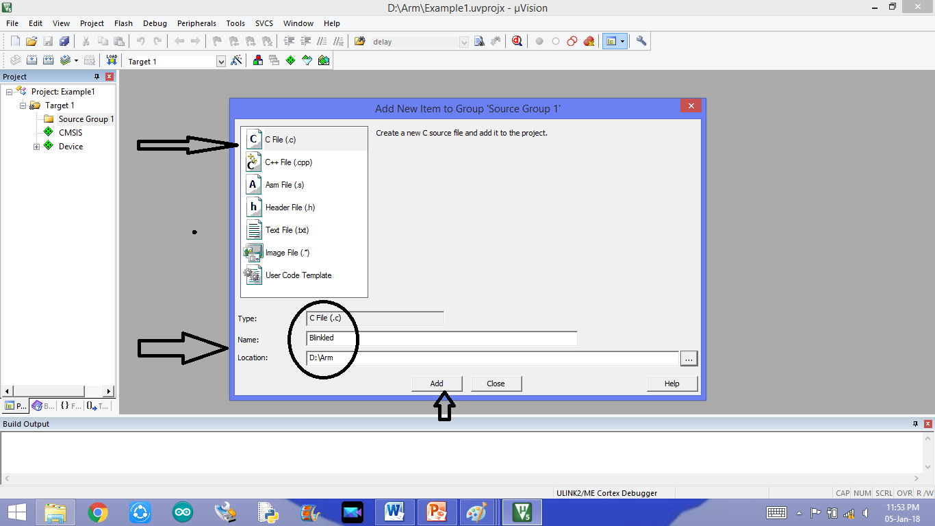
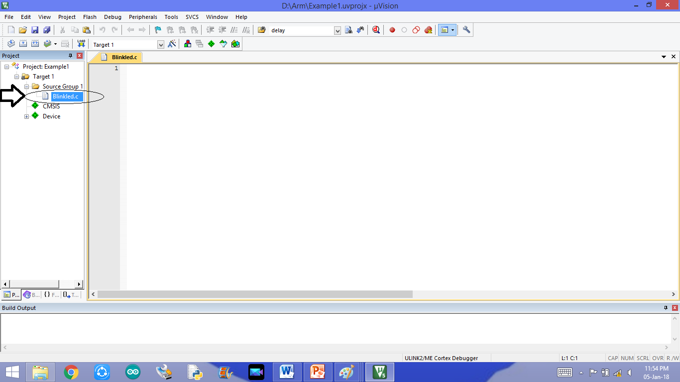
Step 8: The program file, under source group will be added and program editor window will be opens.
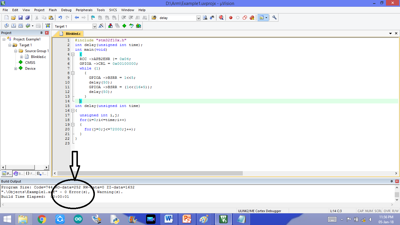
Step 9: After writing program, Build the target files to check the errors.
Step 10:Download the code to the STM32 board

Let us start with small led blinking Program:
Theory of LED
Light emitting diodes (LEDs) are semiconductor light sources. The light emitted from LEDs varies from visible to infrared and ultraviolet regions. They operate on low voltage and power. LEDs are one of the most common electronic components and are mostly used as indicators in circuits. They are also used for luminance and optoelectronic applications.
Based on semiconductor diode, LEDs emit photons when electrons recombine with holes on forward biasing. The two terminals of LEDs are anode (+) and cathode (-) and can be identified by their size. The longer leg is the positive terminal or anode and shorter one is negative terminal.
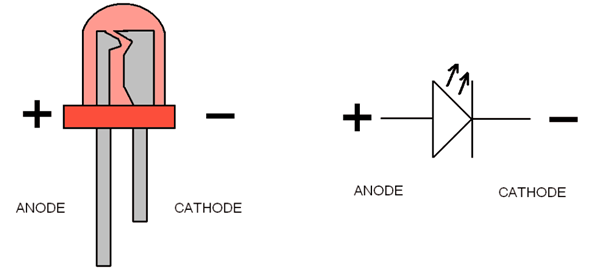
The forward voltage of LED (1.7V-2.2V) is lower than the voltage supplied (5V) to drive it in a circuit. Using an LED as such would burn it because a high current would destroy its p-n gate. Therefore a current limiting resistor is used in series with LED. Without this resistor, either low input voltage (equal to forward voltage) or PWM (pulse width modulation) is used to drive the LED. Get details about internal structure of a LED.
Code
#include “stm32f10x.h” // Including STM Header file
int delay (unsigned int time) // declaring delay function
{
unsignedinti , j ;
for(i=0;i<=time;i++)
{
for(j=0;j<=3910;j++);
}
}
int main(void) // initializing main
{
RCC ->APB2ENR |= 0x04 ;//Reset clock control peripheral clock enabling register
GPIOA->CRH = 0x00000001; // set up configuration register high
while (1)220
{
GPIOA->ODR = 0x0200; // Assigning high value to Output data register
delay(2); // Calling delay function
GPIOA->ODR = 0x0000; // Assigning low value to Output data register
delay(1000);
}
}

