How about controlling your home appliances like Bulb, Motor etc.. just by a single click on your remote that feels cool right!!?? Tenet Technetronics introduces Universal GPIO breakout board which is ready to use Input and Output circuit which are always important to experiment with any micro-controller. The Universal GPIO Board is very useful for beginners, hobbyist and students. It is suitable for carrying out quick experiments with any micro-controller and lets you access numerous peripheral devices. It provides access to pins through male connectors for wiring to the micro-controller development board.
This board has below listed interface circuits to work with:
- 8 LEDs
- 4 Switches
- 1 Potentiometer
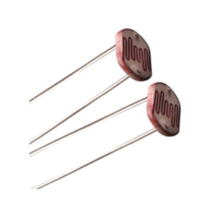
- 1 Light Sensor (using Light Dependent Resistor)
- 1 Temperature Sensor
- 1 Infrared Receiver
- 1 Buzzer
- 1 Seven Segment Display
The TSOP 1738 is a member of IR remote control receiver series. This IR sensor module consists of a PIN diode and a pre amplifier which are embedded into a single package. The output of TSOP is active low and it gives +5V in off state. When IR waves, from a source, with a Centre frequency of 38 kHz incident on it, its output goes low.
Internal Block Diagram:
TSOP module has an inbuilt control circuit for amplifying the coded pulses from the IR transmitter. A signal is generated when PIN photodiode receives the signals. This input signal is received by an automatic gain control (AGC). For a range of inputs, the output is fed back to AGC in order to adjust the gain to a suitable level. The signal from AGC is passed to a band pass filter to filter undesired frequencies. After this, the signal goes to a demodulator and this demodulated output drives an NPN transistor. The collector output of the transistor is obtained at pin 3 of TSOP module.
Members of TSOP17xx series are sensitive to different Centre frequencies of the IR spectrum. For example TSOP1738 is sensitive to 38 kHz whereasTSOP1740 to 40 kHz Centre frequency.
Interfacing:
TSOP 1738 can be easily interfaced with the controllers. Photo modules are 3 pin devices. These pins are assigned for +V (5V), –V (GND) and Output. The pin assignment of TSOP 17… series from the front side (projected side) is Pin 1 Ground, Pin 2 + 5V and pin 3 Output. The photo module requires regulated 5V supply. If the supply voltage increases, the device will be destroyed.
Here we are interfacing TSOP with Arduino to control a bulb using a remote whenever the mute button is pressed the bulb turns on and when the power button is pressed it turns off.
Features of TSOP:
- Photo detector and preamplifier in one package
- Continuous data transmission possible (up to 2400 bps)
- TTL and CMOS compatibility
For more information please visit: www.tenettech.com
For technical query please send an e-mail: info@tenettech.com


